

Practical FPGA Design for Radio Electronics
About the Course
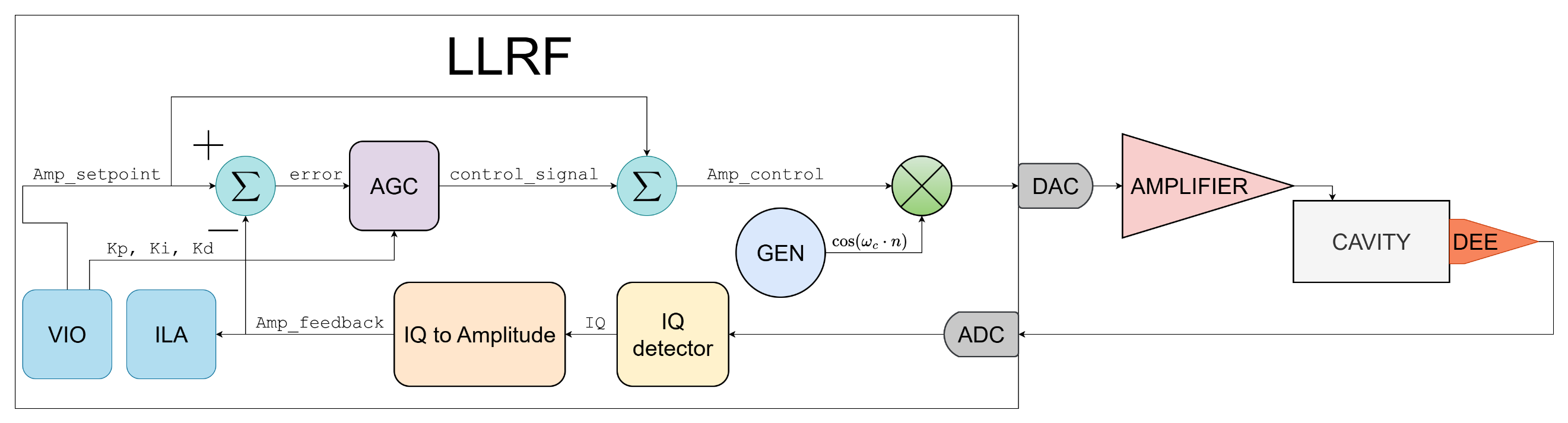
The course introduces the design of digital radio-electronic systems on field-programmable gate arrays (FPGAs). It starts with the basics of the SystemVerilog hardware description language and the Vivado design environment, then moves on to digital signal processing: sine wave generation, filtering, modulation and amplitude detection. The course ends with building a simple LLRF (Low-Level RF) system, that is, stabilization of the radio-frequency field of a cyclotron accelerating system.
Each lesson consists of a short theory part and practice. Algorithms are first modeled in Python, then implemented in SystemVerilog and verified in simulation. Unlike a classical digital logic course, a deep treatment of Boolean algebra and low-level details is not required: the emphasis is on understanding systems, the ideas behind the algorithms and development speed.
What you need to know to complete the course
• fundamentals of calculus, complex numbers and trigonometry;
• no prior knowledge of digital signal processing is needed: it is introduced from scratch in the second lecture;
• basic computer skills; programming experience (for example, in Python) is not required, but it makes learning HDL easier.
Tools used
• the SystemVerilog hardware description language;
• the Xilinx (AMD) Vivado design environment, including simulation;
• Python for algorithm modeling and plotting spectra;
• MATLAB (filterDesigner) for computing FIR and IIR filter coefficients.
The course consists of 10 lessons.
Lessons:
|
1. FPGA and SystemVerilog Basics Result: ability to create a project in Vivado, describe a synchronous module in SystemVerilog, run a behavioral simulation, build a block design and program the board.
|
 |
|
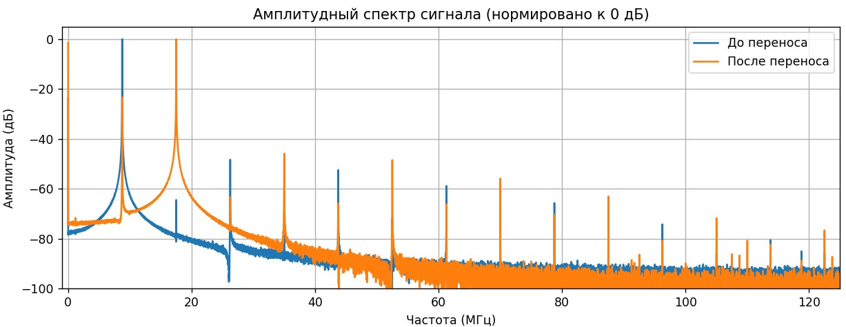
2. Introduction to Digital Signal Processing Result: understanding of the Nyquist frequency, frequency shifting and the signal spectrum. Skill in generating and analyzing signals in Python (numpy, matplotlib), including a real signal from the FPGA ADC.
|
   |
|
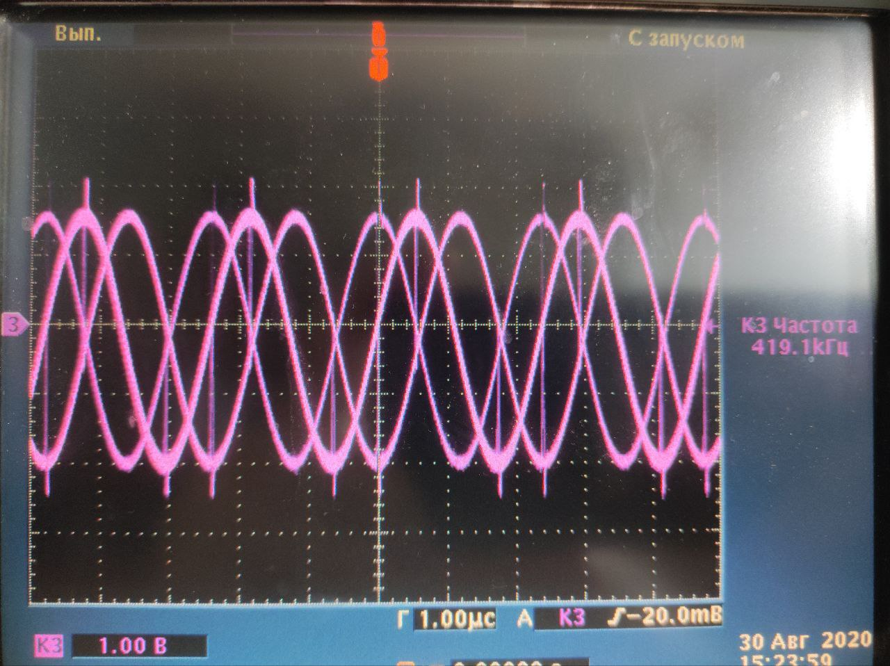
3. Sine Wave Generation: DDS and CORDIC Result: understanding of digital sine wave synthesis (DDS and CORDIC). Experience configuring the DDS Compiler and CORDIC IP blocks in Vivado and checking the signal in simulation and on an oscilloscope. Ability to explain waveform distortions using ILA data.
|
 |
|
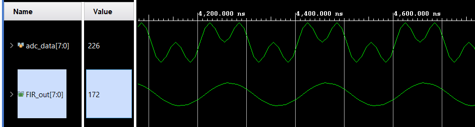
4. Digital Filtering: FIR and IIR Filters Result: understanding of FIR and IIR filters and their frequency responses. Experience implementing a low-pass FIR filter with the FIR Compiler IP block and testing it on a real signal: DAC → ADC → ILA.
|
 |
|
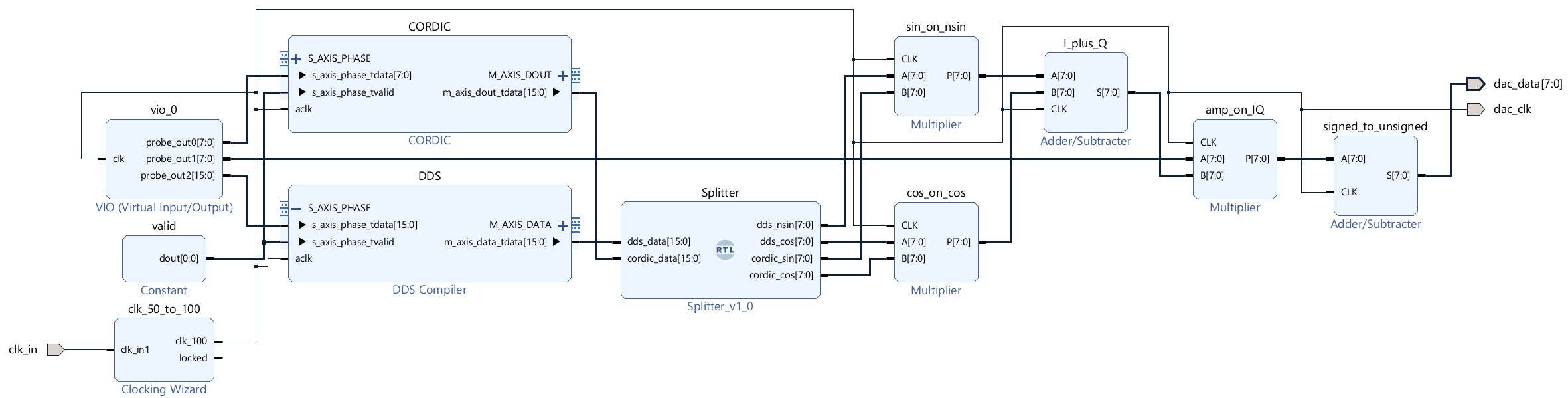
5. Modulation: AM, FM, PSK, QAM Result: understanding of AM, FM, PSK and quadrature (IQ) modulation. Experience building a QAM modulator from the CORDIC and DDS Compiler IP blocks, controlling amplitude, frequency and phase via VIO, and checking the signal with an oscilloscope.
|
 |
|
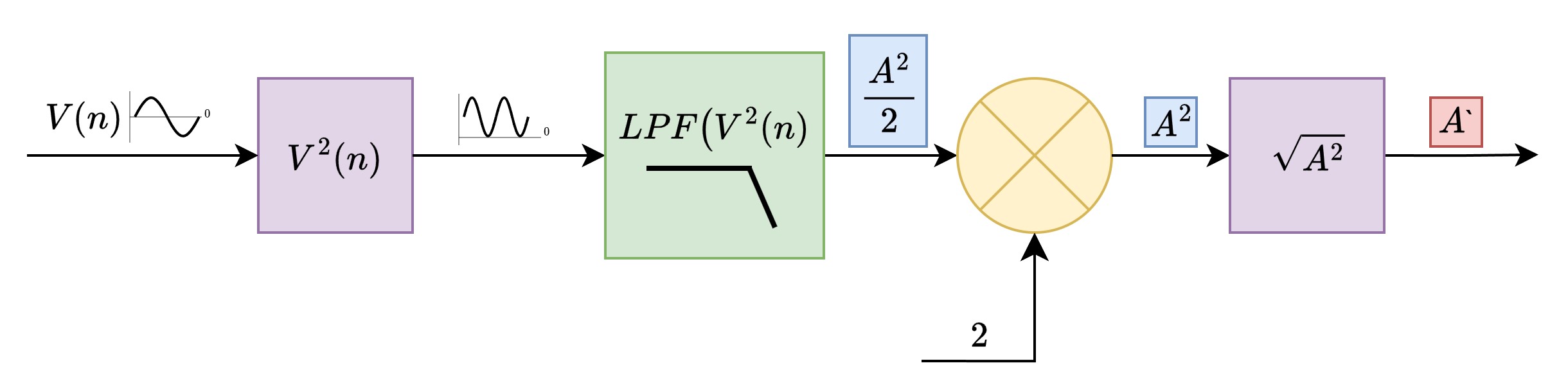
6. Amplitude Detectors No. 1: Diode Bridge and Squared Envelope Result: understanding of the signal envelope. Experience implementing two amplitude detectors (a digital diode bridge and a squared real envelope) with a low-pass filter on FIR Compiler. Skill in collecting data via ILA and analyzing the spectrum and SNR in Python.
|
 |
|
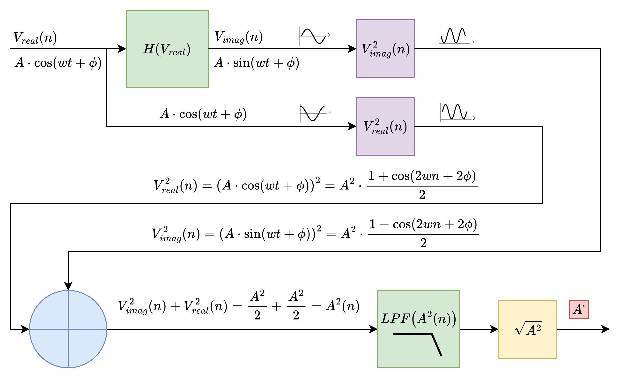
7. Amplitude Detectors No. 2: Hilbert Transform Result: understanding of the analytic signal and the Hilbert transform. Experience designing a Hilbert FIR filter in MATLAB, implementing it with FIR Compiler and comparing its SNR with the previous detectors.
|
 |
|
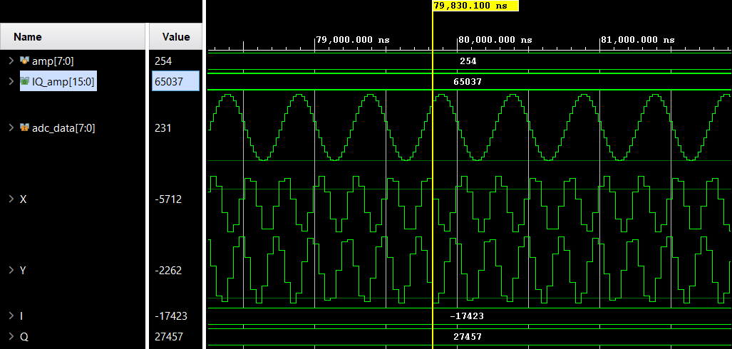
8. Amplitude Detectors No. 3: IQ Demodulation Result: understanding of IQ demodulation. Experience implementing an IQ detector that extracts amplitude and initial phase (a low-pass filter and conversion to polar coordinates with CORDIC) and comparing its SNR with the other methods.
|
 |
|
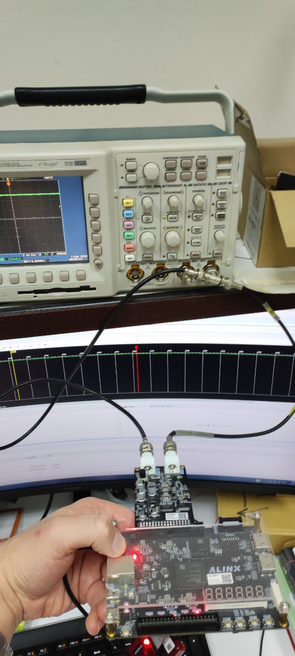
9. PID Controller Result: understanding of the plant, feedback, stability and the terms of a PID controller. Experience implementing a PID controller in SystemVerilog on your own, with a testbench, and testing it by stabilizing a constant voltage at the DAC output (tuning via VIO, observation on an oscilloscope).
|
 |
|
10. Simple Cyclotron LLRF System Result: understanding of the structure of a cyclotron LLRF system. Experience analyzing a complete digital LLRF system on an FPGA (IQ detector, resonator model, PID controller, disturbance source) and evaluating stabilization quality by SNR (an increase from ≈21 to ≈59 dB when the PID is switched on).
|
 |